
Category 6 (Cat 6) Ethernet cables stand as a cornerstone of modern network infrastructure, offering robust and dependable connectivity for both homes and businesses. Proper termination is crucial for optimal performance, and understanding the Cat 6 Cable Diagram is the first step. Just like any Ethernet cable termination, Cat 6 cables adhere to specific wiring diagrams, most commonly the T568A and T568B standards. This guide will delve deep into the Cat 6 wiring diagram, providing a thorough explanation of how to terminate Cat 6 cables effectively, along with essential tips and best practices to ensure a stable and high-performing network.
Understanding Cat 6 Cables
Introduced by the Telecommunications Industry Association (TIA) in 2002, Category 6 cable is a high-performance twisted pair cable standard utilized for Ethernet and other network physical layers. Cat 6 cables are the workhorse of Local Area Networks (LANs) and Wide Area Networks (WANs), frequently connecting computers, routers, switches, printers, scanners, hubs, and a multitude of other network-enabled devices.
A standard unshielded Cat 6 cable comprises four twisted pairs of copper wires, a rip cord for easy jacket removal, and a plastic spline. This spline is a crucial component, physically separating the twisted pairs within the cable to minimize crosstalk – signal interference between adjacent wires – and enhance overall performance. For environments with higher electromagnetic interference (EMI) or radio frequency interference (RFI), shielded Cat 6 (or Cat6a) cables are available. These versions incorporate additional shielding layers, typically around each twisted pair and the entire cable, providing superior protection against external noise and ensuring signal integrity in challenging environments.
Cat 6 cables are further categorized based on their construction and intended application. Solid Cat 6 cables, using solid copper conductors, are typically preferred for permanent installations like in-wall wiring due to their robustness and better conductivity over longer distances. Stranded Cat 6 cables, constructed with multiple thinner copper strands, offer greater flexibility and durability for patch cables and applications requiring frequent movement. Additionally, cable jackets are rated for different fire safety standards: CM (general purpose), CMR (riser-rated for vertical runs), and CMP (plenum-rated for air plenum spaces), ensuring safety and compliance in various installation environments.
Compared to older cable categories like Cat 5e and Cat 5, Cat 6 delivers significant performance improvements. It supports higher bandwidth (up to 250 MHz) and faster data transfer rates, making it capable of Gigabit Ethernet speeds and beyond, crucial for demanding applications like video streaming, large file transfers, and high-bandwidth network applications.
Cat 6 cables are designed to be terminated with RJ45 connectors. To maximize the performance potential of Cat 6, it’s highly recommended to use Cat 6 or Cat 6a rated connectors, which are engineered to handle the cable’s higher frequencies and bandwidth. For shielded Cat 6 cables, shielded RJ45 connectors are essential to maintain the shielding effectiveness throughout the entire connection and minimize interference. While Cat 6 cables are backward compatible with Cat 5 and Cat 5e connectors, using them may limit the overall performance to the lower category’s specifications.
Decoding the Cat 6 Wiring Diagram
A Cat 6 wiring diagram is a visual representation of the precise order in which the eight individual wires within a Cat 6 cable must be arranged when terminating the cable with an RJ45 connector. Adhering to the correct Cat 6 cable diagram is paramount to ensure proper signal transmission and prevent network compatibility issues. Incorrect wiring can lead to slow speeds, dropped connections, or complete network failure.
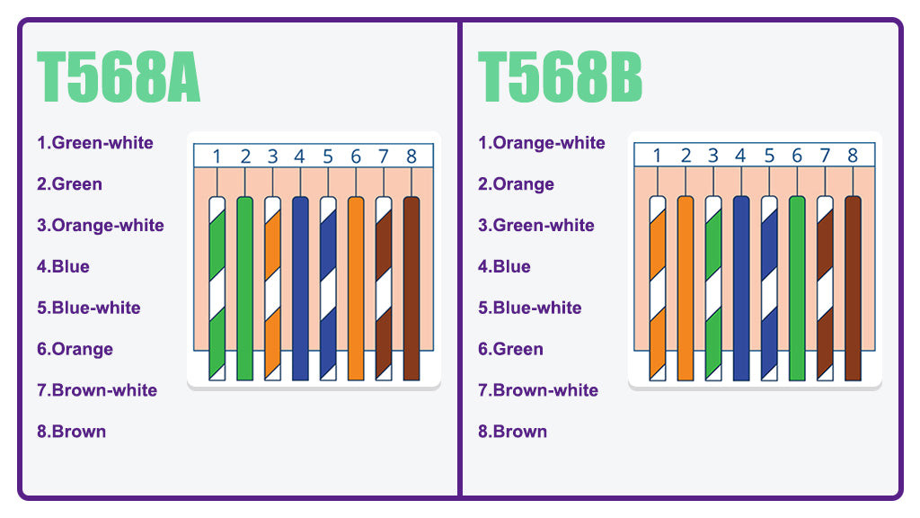
There are two primary wiring standards recognized for Category 6 cables: T568A and T568B. The fundamental difference between these two standards lies in the swapped positions of the green and orange wire pairs. In most standard network applications, the choice between T568A and T568B Cat 6 wiring color codes is largely inconsequential from a performance standpoint. The critical factor is consistency: you must choose one standard and apply it consistently throughout your entire network installation.
In practice, the T568B wiring diagram has become more prevalent for Cat 6 cable termination in commercial and residential settings. However, T568A remains a viable and equally functional alternative.
Another crucial aspect of the Cat 6 wiring diagram is maintaining the same color sequence at both ends of the cable. For a standard “straight-through” patch cable, the same wiring diagram (either T568A or T568B) must be used on both RJ45 connectors. Deviating from this and using T568A on one end and T568B on the other creates a “crossover cable.” Crossover cables are specifically designed for connecting two devices of the same type directly (e.g., computer-to-computer or switch-to-switch) without a hub or switch in between. While crossover cables were more common in older network setups, modern network devices typically support Auto-MDIX, which automatically detects and adjusts for cable type, making straight-through cables with consistent wiring diagrams the standard for most applications today.
 T568A vs T568B Wiring Diagrams for Cat6 Cable
Selecting the Right Cat 6 Wiring Diagram: T568A or T568B?
Choosing between the T568A and T568B Cat 6 wiring diagrams often comes down to understanding legacy compatibility and existing infrastructure, though in many modern scenarios, the choice is less critical.
-
T568A and Legacy Compatibility: The ANSI/TIA standards body initially recommended T568A for residential installations primarily because it offered backward compatibility with older telecommunications technologies, such as traditional fax machines and analog wireless telephones that utilized RJ45 connectors. If your network needs to interface with such legacy devices, T568A might be the preferred choice.
-
T568B and Modern Network Equipment: The majority of contemporary network equipment, including routers, switches, computers, and servers, are designed and manufactured with the T568B color code as the default standard. This widespread adoption makes T568B the more commonly used standard in most new installations.
-
Maintaining Consistency in Existing Installations: If you are expanding or modifying an existing network, the most crucial factor is to identify the wiring standard already in use. Inspect existing cable terminations to determine whether T568A or T568B was used. To ensure seamless integration and prevent potential issues, maintain consistency by using the same wiring diagram for all new Cat 6 cable terminations within that network.
-
Crossover Cables and Modern Networks: Historically, crossover cables were essential for direct device-to-device connections. However, with the prevalence of Auto-MDIX (Automatic Medium Dependent Interface Crossover) in modern network interfaces, most devices can automatically detect and adjust to either straight-through or crossover cables. Therefore, in the vast majority of contemporary network deployments, straight-through cables using either T568A or T568B (consistently on both ends) are sufficient and crossover cables are rarely necessary.
Step-by-Step Guide: How to Terminate a Cat 6 Cable
Once you have a clear understanding of the Cat 6 wiring diagram and have chosen either T568B (the standard used in this tutorial) or T568A, the next step is to learn the practical process of Cat 6 Ethernet cable termination. Follow this detailed, step-by-step tutorial to successfully terminate your Cat 6 cables.
Preparation is Key: Before you begin, gather all the necessary materials and specialized tools required for terminating Cat 6 cables. Using the right tools will significantly simplify the process and ensure reliable connections.
- Pass-through Cat 6 RJ45 Connectors: Pass-through RJ45 connectors are highly recommended, especially for beginners. Their design allows the wires to pass completely through the connector before crimping, making it easier to verify the correct wire order and reducing wiring errors.
- Strain Relief Boots: Strain relief boots are essential accessories that slide over the RJ45 connector and cable jacket. They provide protection to the delicate connector and the cable termination point from dust, physical stress, and damage, extending the lifespan and reliability of the connection.
- Pass-through RJ45 Crimping Tool: A specialized pass-through RJ45 crimping tool is specifically designed for use with pass-through connectors. These tools typically combine crimping, and wire cutting functions into one, streamlining the termination process.
- Mini Wire Stripper: A mini wire stripper with an adjustable blade is indispensable for precisely removing the outer jacket of the Cat 6 cable without damaging the delicate inner copper wires. Adjustable blades allow you to customize the stripping depth for different cable types and thicknesses.
- Cable Snips (or Flush Cutters): Cable snips or flush cutters are used for cleanly cutting the rip cord, the center spline, and trimming the excess wires after they pass through the RJ45 connector. Sharp, precise cuts are important for a clean and professional termination.
- Network Cable Tester: A network cable tester is a crucial tool for verifying the integrity and proper wiring of your terminated Cat 6 cable. It tests each pin connection to ensure continuity and correct wiring according to the chosen standard, helping to identify and troubleshoot any errors before deployment.
 Prepare Tools and Materials for Cat6 Cable Termination
Step 1: Begin by sliding the strain relief boot onto the Cat 6 cable before installing the RJ45 connector. Forgetting this step will require you to cut off the connector and restart the termination process.
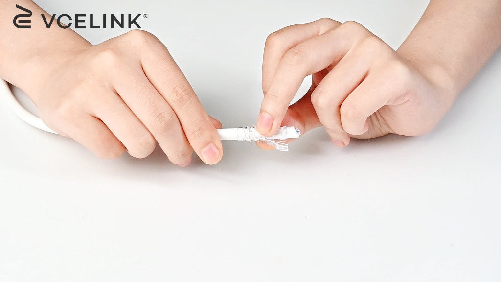 Slide Strain Relief Boot onto Cat6 Cable
Step 2: Using the mini wire stripper, carefully strip off approximately 1 inch of the outer cable jacket from the end of the Cat 6 cable. Exercise caution and adjust the stripping blade depth to avoid nicking or damaging the insulation of the individual copper wires inside. Set aside the removed jacket piece, as it can be helpful for straightening the wires later.
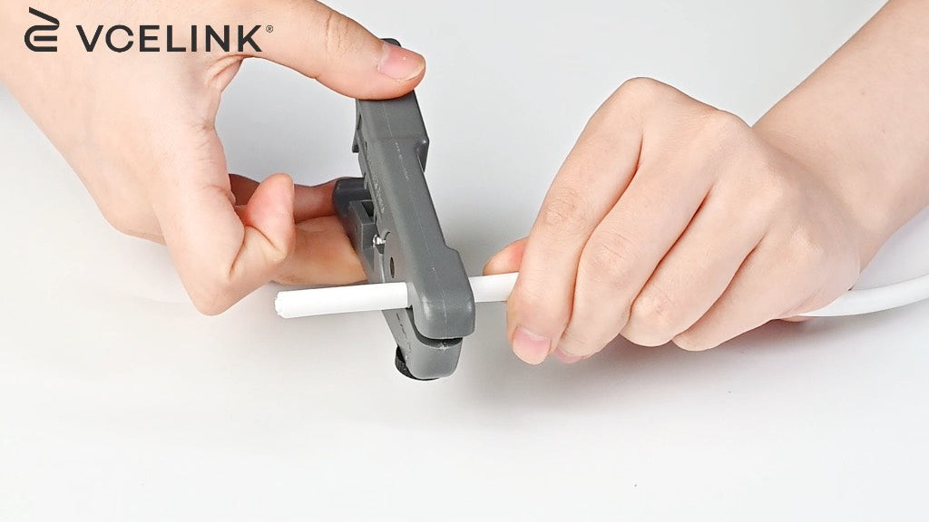 Strip Off Cat6 Cable Jacket Using Wire Stripper
Step 3: Locate the rip cord running lengthwise under the cable jacket and carefully cut it using the cable snips. Also, cut away the plastic center spline that separates the twisted pairs. These components are no longer needed after stripping and can be discarded.
 Cut Rip Cord and Center Spline of Cat6 Cable
Step 4: Carefully untwist each of the four twisted pairs of wires. Use the piece of removed cable jacket or your fingers to gently straighten each of the eight individual copper wires as much as possible. Straightening the wires makes it significantly easier to arrange them in the correct order and insert them into the RJ45 connector.
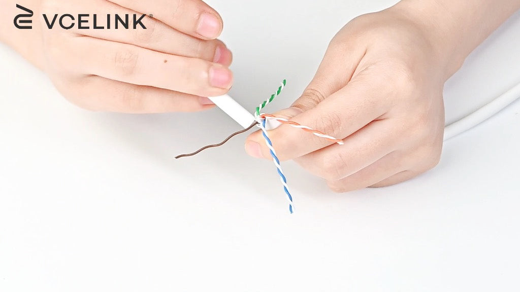 Untwist and Straighten Copper Wires of Cat6 Cable
Step 5: Arrange the straightened wires in the correct sequence according to your chosen Cat 6 wiring diagram. For this tutorial, we are using the T568B standard: Orange-white, Orange, Green-white, Blue, Blue-white, Green, Brown-white, Brown. Double-check the color order to ensure accuracy.
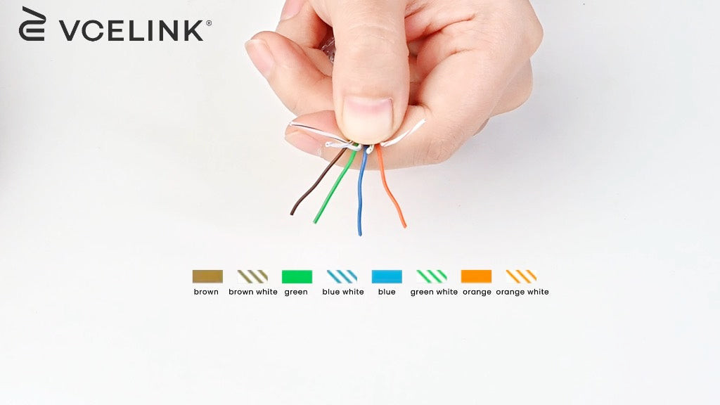 Arrange Wires According to T568B Cat6 Wiring Diagram
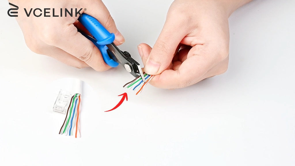
Step 6: Using the cable snips, trim the ends of the arranged wires to create a clean, even cut. An angled cut, rather than a straight cut, can sometimes facilitate easier insertion of the wires into the RJ45 connector. Cut the wires to a length that will allow them to fully insert into the pass-through RJ45 connector and extend just beyond the front.
Cut Rip Cord and Center Spline of Cat6 Cable
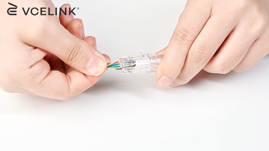
Step 7: Carefully insert the arranged and trimmed wires into the pass-through RJ45 connector. Push firmly and evenly until each wire is fully inserted and visible through the front of the connector. Visually verify that the wire order is correct as you insert them into the connector.
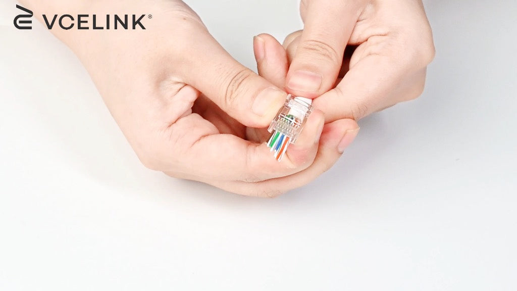 Insert Wires into Pass-through RJ45 Connector
Step 8: Double-check the wire sequence one last time by looking at the wires through the front of the pass-through connector. Ensure they are in the correct T568B (or T568A) order. Slide the strain relief boot forward over the RJ45 connector and cable jacket, seating it securely.
 Install Strain Relief Boot onto RJ45 Connector and Cable
Step 9: Prepare for the crimping process. A helpful tip is to gently twist the excess wires protruding from the front of the connector together. This makes them easier to insert into the crimping tool and ensures a clean cut.
 Twist Excess Wires Before Crimping RJ45 Connector
Step 10: Insert the RJ45 connector into the pass-through RJ45 crimping tool. Apply firm, even pressure to fully crimp the connector. The crimping action will simultaneously secure the wires within the connector and cut off the excess wires extending through the front of the pass-through connector.
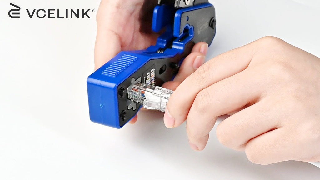 Crimp RJ45 Connector Using Pass-through Crimping Tool
Step 11: Repeat steps 1 through 10 on the other end of the Cat 6 cable. Crucially, use the same Cat 6 wiring diagram (T568B in this case) for the connector on the second end to create a straight-through cable.
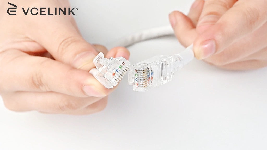 Terminate RJ45 Connector on the Other End of Cat6 Cable
Step 12: The final and essential step is to test your newly terminated Cat 6 Ethernet cable using a network cable tester. Connect one end of the cable to the main unit and the other end to the remote unit of the tester. Activate the tester and observe the indicator lights. A properly wired cable will show continuity and correct wiring sequence for all eight pins, confirming a successful termination.
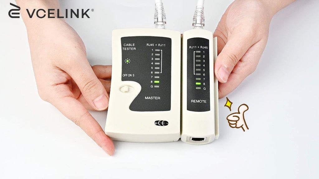 Test Cat6 Cable with Network Cable Tester
Troubleshooting Common Cat 6 Wiring Issues
Even with careful termination, issues can occasionally arise, especially for those new to Cat 6 cabling. Here are some common problems and troubleshooting tips:
-
Incorrect Wire Order: The most frequent issue is an incorrect wire sequence in the RJ45 connector. This can result in network connectivity problems, slow speeds, or no connection at all. Carefully double-check the wire order against your chosen wiring diagram (T568A or T568B) before crimping. Pass-through connectors help mitigate this by allowing visual verification. If testing reveals incorrect wiring, you’ll need to cut off the connector and re-terminate.
-
Poor Contact: Sometimes, even with correct wiring, the RJ45 connector pins may not make proper contact with the copper conductors. This can be due to insufficient crimping pressure, damaged connector pins, or improperly stripped wires. Ensure you use a quality crimping tool and apply firm, even pressure during crimping. If you suspect poor contact, re-terminate the connector.
-
Cable Jacket Stripped Too Far: Stripping too much of the cable jacket exposes excessive lengths of untwisted wires. This increases crosstalk and signal degradation, potentially affecting network performance, especially at higher speeds and longer distances. Strip only the recommended amount of jacket (around 1 inch) to minimize untwisted wire length.
-
Damaged Wires: Nicking or cutting the insulation of the individual copper wires during stripping can also cause signal degradation and shorts. Use a quality wire stripper with an adjustable blade and exercise caution when stripping the jacket. If you suspect wire damage, re-terminate.
-
Unshielded Cable in High EMI Environment: In environments with significant electromagnetic interference (e.g., near power lines, motors, or fluorescent lighting), unshielded Cat 6 cable may experience performance issues. Consider using shielded Cat 6 (or Cat 6a) cable and shielded connectors in such environments to minimize interference and maintain signal integrity.
If you frequently perform field terminations, field termination plugs (also known as reusable or tool-less connectors) can be beneficial. These connectors are designed for easier field installation and can often be re-terminated multiple times, saving time and materials when troubleshooting or making changes.
To ensure optimal network performance and longevity, always use high-quality Cat 6 cables and connectors, terminate them correctly following a consistent wiring diagram, and adhere to the maximum recommended cable length of 100 meters (328 feet) for Cat 6 Ethernet runs.
Conclusion: Mastering Cat 6 Wiring Diagrams for Reliable Networks
Understanding and correctly applying Cat 6 wiring diagrams is fundamental to building reliable and high-performance Ethernet networks. Whether you’re setting up a home network or wiring a commercial building, mastering Cat 6 cable termination is a valuable skill. By following the guidelines and step-by-step instructions outlined in this guide, even beginners can confidently create Cat 6 patch cables and ensure robust network connectivity. Choosing the appropriate wiring diagram (T568A or T568B), maintaining consistency, using quality components and tools, and testing your terminations are all key to achieving a stable and efficient Cat 6 network infrastructure.
Frequently Asked Questions (FAQs)
Does a Cat 6 cable use all eight wires?
Yes, Cat 6 cables are designed for Gigabit Ethernet and utilize all eight wires for full performance. Pairs 1 and 2 are used for data transmission, pairs 3 and 6 for data reception, and pairs 4, 5, 7, and 8 are used for additional data transmission, Power over Ethernet (PoE) applications, and to improve signal-to-noise ratio. While some older Ethernet standards only used four wires, Cat 6 leverages all eight for maximum bandwidth and functionality.
Can I run Cat 6 cables in the same conduit as electrical wires?
It is generally not recommended to run Cat 6 cables in the same conduit as electrical power wires. Power lines can induce electromagnetic interference (EMI) into unshielded Cat 6 cables, potentially degrading network performance. While Cat 6 cables can run parallel to low-voltage cables, unshielded Cat 6 should be kept at least 12 inches (30 cm) away from power lines to minimize EMI. If running Cat 6 and electrical wires in close proximity is unavoidable, use shielded Cat 6 or Cat 6a cable and ensure proper grounding, or use separate conduits with sufficient physical barriers. Always consult local electrical codes and regulations for specific requirements.
What are the consequences of incorrectly wiring a Cat 6 cable?
Incorrectly wiring a Cat 6 cable can lead to a range of network problems, from minor performance issues to complete network failure. Common consequences include:
- Network Failure: In some cases, incorrect wiring can prevent network connectivity altogether.
- Slow Network Speed: Miswiring can significantly reduce data transfer speeds, potentially dropping Gigabit Ethernet speeds down to much slower rates.
- Transmission Errors: Incorrect wiring can introduce data corruption and transmission errors, leading to dropped packets and unreliable network performance.
- Interference and Crosstalk: Improperly wired pairs can increase crosstalk and signal interference, further degrading performance and potentially causing intermittent disconnections.
It is crucial to test every terminated Cat 6 cable with a network cable tester to verify correct wiring and prevent these issues.
For more in-depth information on networking best practices and cable management, explore our blogs. VCELINK provides general information for website visitors, but it is not a substitute for professional networking advice. Consult with a qualified network technician for specific needs and complex installations.