Category 6 Ethernet cables are a cornerstone of modern network infrastructure, offering robust and dependable connectivity for both homes and businesses. Proper termination of these cables, guided by either the A or B wiring standard, is essential for optimal performance. This article provides a comprehensive guide to Cat 6 Wiring Diagrams, detailing the termination process and offering valuable tips for successful installations.
Delving into Cat 6 Cables
Introduced by the Telecommunications Industry Association (TIA) in 2002, Category 6, commonly known as Cat6, represents a high-standard twisted pair cable designed for Ethernet and other network physical layers. These cables are the workhorse of Local Area Networks (LANs) and Wide Area Networks (WANs), frequently used to establish connections between computers, routers, switches, printers, scanners, hubs, and a variety of other network devices.
A standard unshielded Cat6 cable is constructed with four twisted pairs of wires, a rip cord for easy jacket removal, and a spline – a plastic divider – that separates the twisted pairs to minimize crosstalk, a phenomenon that can degrade signal quality. For environments with higher electromagnetic interference (EMI) or radio-frequency interference (RFI), shielded Cat6 cables are available, incorporating additional layers of shielding to protect signal integrity.
Cat6 cables can be further categorized based on their construction and intended use. For instance, solid Cat6 cables, utilizing solid copper conductors, are typically preferred for permanent installations within walls or ceilings, offering superior electrical performance over longer distances. Stranded Cat6 cables, with multiple strands of copper wire per conductor, provide greater flexibility and durability for patch cables and applications where frequent movement is expected. Furthermore, cable jacket ratings, such as CM (general purpose), CMR (riser-rated for vertical runs), and CMP (plenum-rated for air-handling spaces), dictate where specific Cat6 cables can be safely installed based on fire safety regulations. Cat6 cables mark a significant advancement over older standards like Cat5e and Cat5, delivering enhanced bandwidth and faster data transfer speeds, making them a future-proof choice for network infrastructure.
Cat6 cables are designed to be used with RJ45 connectors. While Cat6 cables can technically be used with Cat5 and Cat5e connectors due to backward compatibility, it’s highly recommended to use Cat6 connectors to unlock the full performance potential of Cat6 cabling. For shielded Cat6 cables, shielded Cat6 connectors are crucial to maintain the shielding effectiveness throughout the entire cable run and minimize interference.
Understanding the Cat 6 Wiring Diagram
A Cat6 wiring diagram serves as a visual blueprint, illustrating the precise order in which individual wires must be arranged when terminating Cat6 cables into RJ45 connectors. Adhering strictly to the correct Cat6 cable diagram is not just recommended—it’s essential to prevent network compatibility issues and ensure reliable data transmission.
Two primary wiring standards govern Category 6 cable termination: T568A and T568B. The fundamental difference between these two standards lies in the swapped positions of the green and orange wire pairs. In most practical network scenarios, the choice between T568A and T568B Cat6 wiring color codes is largely inconsequential from a performance standpoint. The critical factor is consistency: select either T568A or T568B based on your preference or existing infrastructure and maintain that standard throughout the entire network installation. In practice, the T568B wiring diagram has become more prevalent for Cat6 cable termination in commercial and residential settings.
Another vital aspect of the Cat6 wiring diagram is ensuring color sequence uniformity at both ends of the cable. For a standard “straight-through” cable, the same wiring diagram (either T568A or T568B) must be meticulously followed at both termination points. Deviating from this principle by using T568A on one end and T568B on the other results in the creation of a crossover cable. Crossover cables serve a specific purpose—directly connecting two devices of the same type, like two computers or two switches, without an intermediary hub or switch—but are not the standard configuration for most network connections.
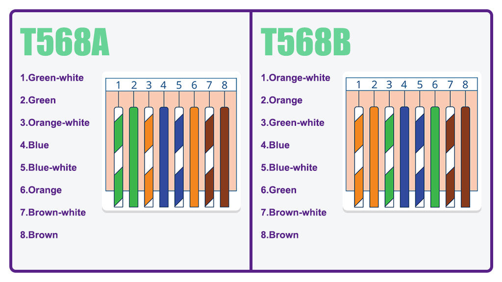 Diagram illustrating the T568A and T568B Cat6 wiring standards side-by-side, highlighting the color code differences and pin assignments.
Selecting the Right Cat 6 Wiring Diagram: T568A vs. T568B
Choosing between the T568A and T568B wiring diagrams often comes down to understanding the specific context of your network installation and considering existing infrastructure.
-
Legacy Compatibility (T568A): The ANSI/TIA standard previously recommended T568A for residential installations primarily due to its backward compatibility with older telecommunications technologies, such as traditional fax machines and analog wireless telephones. If your network needs to interface with such legacy devices, T568A might be the preferred choice to ensure compatibility.
-
Modern Network Standard (T568B): However, the vast majority of modern network equipment manufactured today is designed and configured to utilize the T568B color code. This has led to T568B becoming the de facto standard in most contemporary network deployments. For new installations using predominantly modern devices, T568B is generally the more practical and widely adopted option.
-
Maintaining Existing Consistency: In situations where Cat6 cables are being added to an already established network, the most crucial factor is to identify the wiring standard used in the existing infrastructure. Inspect the currently terminated cables and diligently adhere to the same wiring diagram (either T568A or T568B) to maintain consistency and prevent potential network disruptions or performance issues.
-
Straight-Through vs. Crossover Cables: Historically, crossover cables, wired with T568A on one end and T568B on the other, were essential for direct device-to-device connections without a central networking device. However, modern network interfaces have largely moved beyond this requirement. Most contemporary network devices now incorporate auto-MDI/MDI-X (Medium Dependent Interface/Medium Dependent Interface Crossover) sensing technology. This intelligent feature automatically detects the cable wiring and configures the device’s ports accordingly, effectively eliminating the need for crossover cables in most common scenarios. In almost all typical network setups today, straight-through cables, using the same wiring diagram at both ends, are sufficient and recommended.
Step-by-Step Guide to Terminating a Cat 6 Cable (T568B Standard)
With a solid understanding of Cat6 wiring diagrams, the next crucial step is mastering the physical termination process. This section provides a detailed, step-by-step tutorial for terminating a Cat6 Ethernet cable, utilizing the widely adopted T568B wiring scheme.
Preparation: Gather Your Tools and Materials
Before commencing the termination process, ensure you have all the necessary tools and components readily accessible.
- Pass-through Cat6 RJ45 Connectors: Opt for pass-through RJ45 connectors designed for Cat6 cables. These connectors simplify the termination process, especially for beginners, by allowing wires to extend through the connector end, making wire order verification and crimping more straightforward and reducing the likelihood of wiring errors.
- Strain Relief Boots: Strain relief boots are highly recommended. These small, flexible sleeves slide over the RJ45 connector and cable, providing protection against dust, physical stress at the cable-connector junction, and accidental damage, thus extending the lifespan and reliability of the terminated cable.
- Pass-through RJ45 Crimping Tool: A specialized pass-through RJ45 crimping tool is essential for securely crimping the RJ45 connector onto the Cat6 cable. These tools are designed to not only crimp the connector pins but also to cleanly cut off the excess wires extending through the pass-through connector.
- Mini Wire Stripper: A mini wire stripper with an adjustable blade is indispensable for precisely removing the outer jacket of the Cat6 cable without damaging the delicate inner wires. Adjustability is key to accommodate different cable types and prevent accidental nicks or cuts to the conductors.
- Cable Snips (or Utility Knife): Cable snips or a sharp utility knife are needed for cutting the cable jacket’s rip cord (if present) and trimming the internal spline of the Cat6 cable. Precision and caution are important to avoid damaging the insulation of the inner wires.
- Network Cable Tester: A network cable tester is a vital tool for verifying the integrity and proper wiring of the terminated Cat6 cable. Testers, often compatible with both RJ45 and RJ11 connectors, quickly confirm continuity and correct pin assignments, saving time and frustration in troubleshooting network connectivity issues.
 Image showcasing all the tools and materials required for Cat6 cable termination, neatly arranged on a workbench.
Step 1: Begin by sliding the strain relief boot onto the Cat6 cable before attaching the RJ45 connector. Forgetting this step is a common mistake that necessitates re-termination.
 Image illustrating the action of sliding a strain relief boot onto a Cat6 cable.
Step 2: Employ the mini wire stripper to carefully remove approximately one inch of the Cat6 cable’s outer jacket. Exercise caution and adjust the stripper blade depth to avoid nicking or cutting the insulation of the inner copper wires. Set aside the removed jacket portion; it can be helpful later to straighten wires.
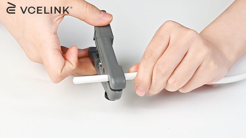 Image depicting the process of stripping the outer jacket from a Cat6 cable using a wire stripper.
Step 3: Locate the rip cord (a thin string within the cable jacket) and the center spline (the plastic divider). Use cable snips or a utility knife to cut and remove both the rip cord and the spline as close to the jacket stripping point as possible.
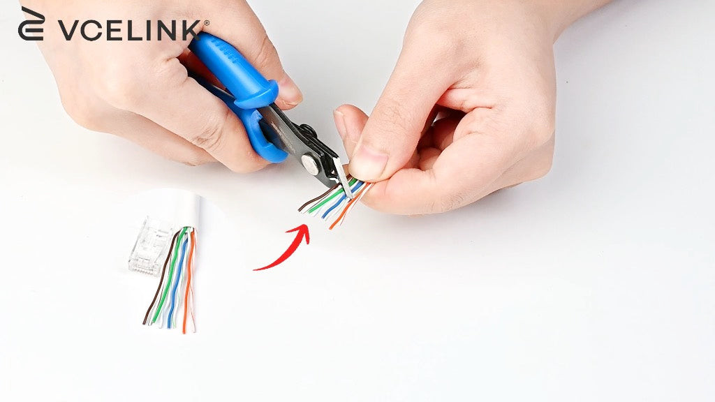 Image showing the removal of the rip cord and center spline from a Cat6 cable using cable snips.
Step 4: Gently untwist the eight individual wires of the Cat6 cable. Utilize the piece of removed cable jacket or your fingers to straighten each of the copper wires as much as possible. Straight wires are crucial for easy insertion into the RJ45 connector.
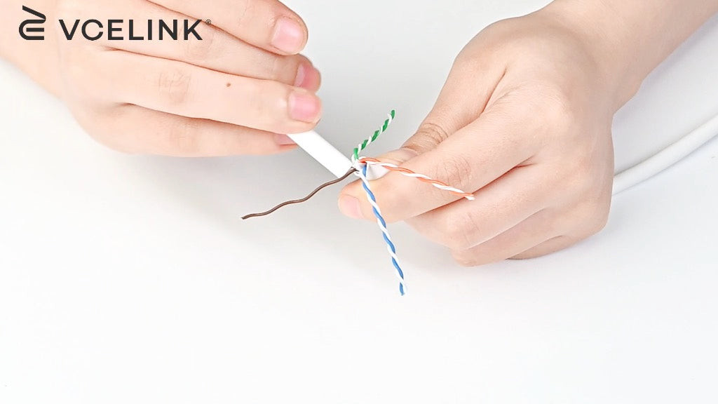 Image displaying the untwisting and straightening of the individual copper wires of a Cat6 cable.
Step 5: Arrange the straightened wires in the correct T568B wiring sequence: Orange/White, Orange, Green/White, Blue, Blue/White, Green, Brown/White, Brown. Maintain this precise order for proper network functionality.
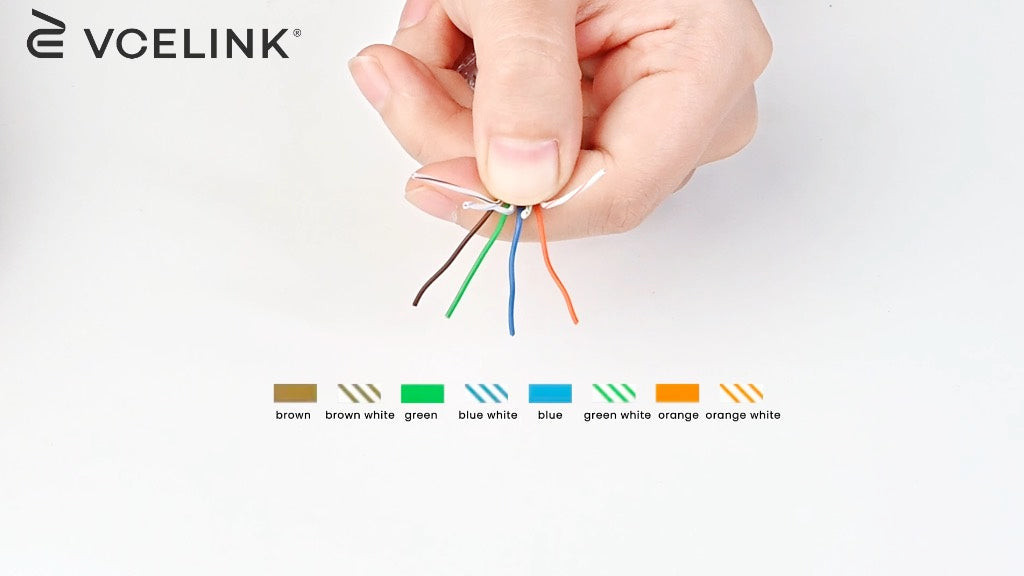 Image illustrating the arrangement of Cat6 wires according to the T568B wiring standard.
Step 6: Using the cable snips, carefully cut the tips of the arranged wires to create a clean, even end. An angled cut is often recommended as it can facilitate smoother insertion into the RJ45 connector compared to a straight cut.
Image showing the removal of the rip cord and center spline from a Cat6 cable using cable snips.
Step 7: Firmly and carefully insert the arranged and trimmed wires into the pass-through RJ45 connector. Ensure that each wire is guided into its designated pin slot and passes completely through the connector, emerging from the front.
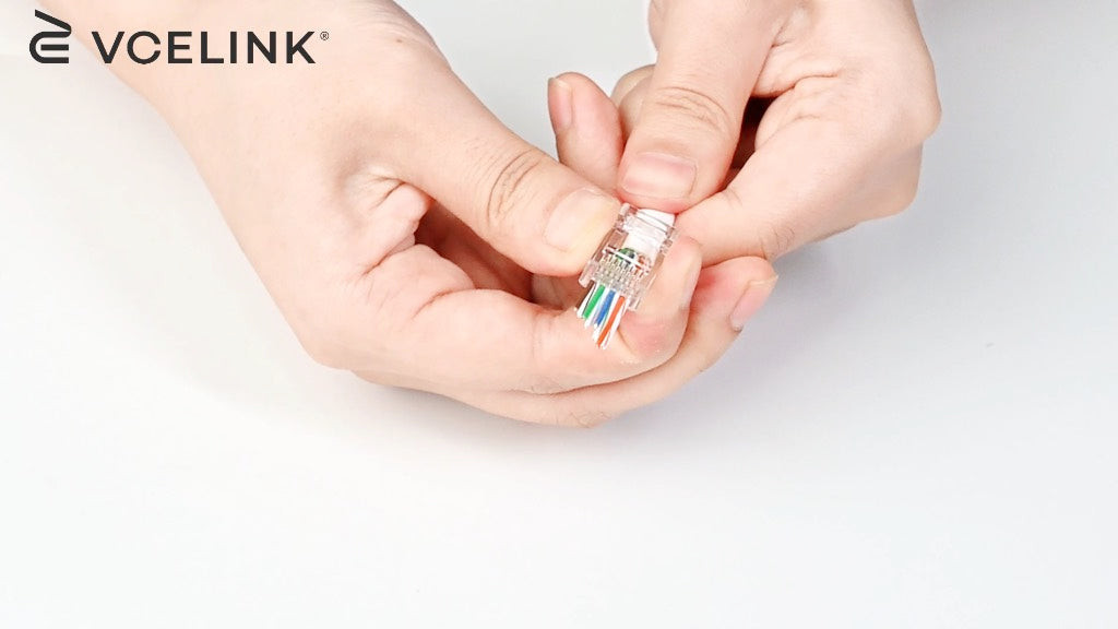 Image showing the insertion of Cat6 wires into a pass-through RJ45 connector.
Step 8: Visually double-check the wire sequence through the pass-through end of the RJ45 connector to confirm it adheres to the T568B standard. Then, slide the strain relief boot forward, positioning it over the rear of the RJ45 connector.
 Image depicting the installation of the strain relief boot onto the RJ45 connector after wire insertion.
Step 9: Prepare for the crimping stage. A helpful technique is to gently twist the excess wires protruding from the front of the RJ45 connector. This slight twist aids in their neat insertion into the crimping tool’s cavity.
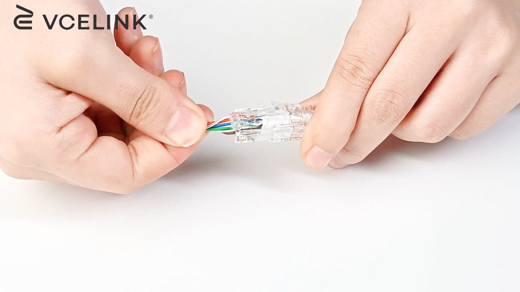 Image illustrating the twisting of excess wires at the front of the RJ45 connector in preparation for crimping.
Step 10: Insert the RJ45 connector, with the cable and wires in place, into the pass-through RJ45 crimping tool. Firmly squeeze the crimping tool handles to crimp the connector pins, establishing secure electrical contact and simultaneously cutting off the excess wires extending beyond the connector face.
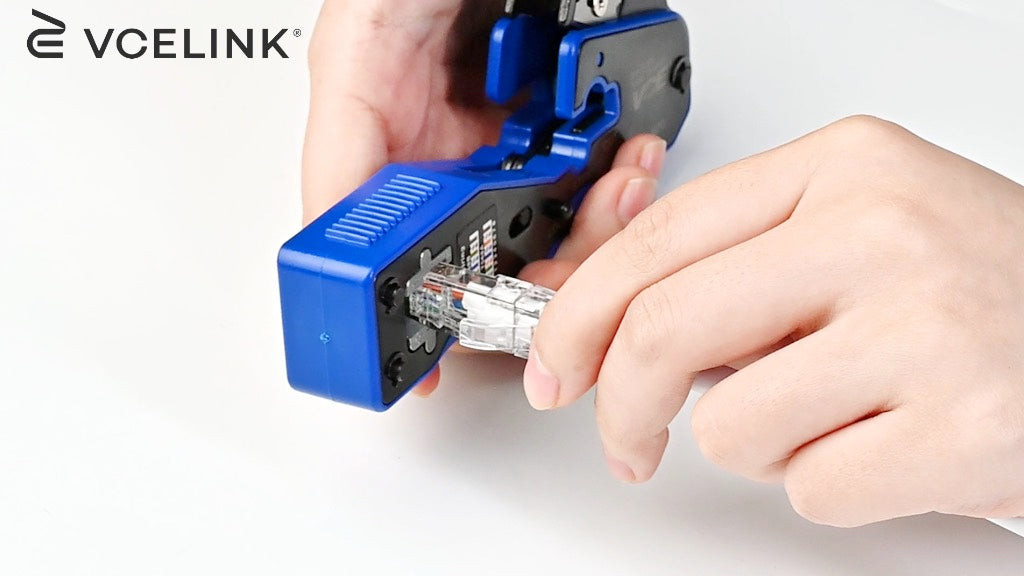 Image showing the crimping process of the RJ45 connector using a pass-through crimping tool.
Step 11: Repeat steps 1 through 10 to terminate the RJ45 connector on the opposite end of the Cat6 cable. Crucially, use the same Cat6 wiring diagram (T568B in this tutorial) for both ends to create a straight-through cable.
 Image demonstrating the completed termination of an RJ45 connector on a Cat6 cable.
Step 12: The final and essential step is testing. Utilize the network cable tester to verify the newly terminated Cat6 Ethernet cable. The tester will confirm proper wire continuity and correct pin assignments, ensuring the cable is ready for reliable network use.
 Image depicting the testing of a terminated Cat6 cable using a network cable tester.
Troubleshooting Common Cat6 Wiring Issues
Even with careful execution, Cat6 cable termination can sometimes encounter challenges, especially for those new to the process. Common issues include:
- Pin Contact Problems: The RJ45 connector’s contact pins may not always make proper contact with the copper conductors. This can be due to incorrect wire insertion, insufficient crimping pressure, or using damaged connectors.
- Incorrect Wire Sequence: A frequent error is an incorrect wire sequence, deviating from the chosen T568A or T568B wiring diagram. Even a single misplaced wire can lead to network connectivity problems.
In these instances, the best course of action is to replace the faulty Cat6 connector and re-terminate the cable end. Pass-through connectors are helpful in visually confirming wire order before crimping, reducing this type of error.
For field terminations or situations where repeated terminations might be necessary, field termination plugs are a valuable alternative to standard RJ45 connectors. Field termination plugs are designed for multiple uses, allowing for easier troubleshooting and re-termination without sacrificing cable length.
In environments susceptible to electromagnetic interference, employing shielded Cat6 cables and shielded connectors is highly recommended. Furthermore, always prioritize quality cables and connectors, adhere to correct termination techniques, and ensure cable runs stay within the recommended 100-meter limit to achieve optimal and dependable network performance.
Conclusion: Mastering Cat 6 Wiring for Network Success
Cat6 wiring diagrams are indispensable knowledge for anyone involved in Ethernet cable installation and network maintenance. Cat6 cables remain a top recommendation for both home and business networks due to their performance and reliability. By mastering the principles of Cat6 wiring and practicing correct termination techniques, even individuals new to cable termination can confidently create Cat6 patch cables and build robust network infrastructures.
Frequently Asked Questions (FAQs)
Does a Cat6 cable utilize all eight wires?
Yes, Cat6 cables are designed for Gigabit Ethernet and typically use all eight wires for full performance. Pairs 1 and 2 are used for data transmission, and pairs 3 and 6 are used for data reception. Pairs 4/5 and 7/8 are often used for additional data transmission, Gigabit Ethernet, or Power over Ethernet (PoE) applications. Even when used with older Ethernet standards, Cat6 cables generally still utilize all eight wires for optimal signal integrity, even if the older standards don’t require them all.
Is it safe to run Cat6 cables alongside electrical wires in the same conduit?
Running Cat6 cables in the same conduit as electrical wires is generally discouraged unless specific precautions are taken. While Cat6 cables can be run parallel to low-voltage cables, unshielded Cat6 cables should ideally be kept at least 12 inches (approximately 30 cm) away from power lines to minimize the risk of electromagnetic interference (EMI). Avoid running Cat6 cables and electrical wires in the same conduit unless there is a sufficient grounded barrier or separation method in place to effectively shield the network cable from electrical noise and potential hazards. Always consult local electrical codes and regulations for specific guidance.
What are the potential consequences of miswiring a Cat6 cable?
Incorrectly wiring a Cat6 cable can lead to a range of network problems, from complete network failure to significantly reduced network speeds and data transmission errors. Miswiring disrupts the balanced signal transmission that twisted pair cables rely on, leading to signal degradation, increased crosstalk, and unreliable network performance. Inconsistent wiring across a network can also create difficult-to-diagnose intermittent connectivity issues.
For more in-depth information and related topics, explore our blogs. Please note that while VCELINK provides general information to assist our customers and website visitors, it is not a substitute for professional networking advice.