
Category 6 (Cat6) Ethernet cables are the backbone of modern network infrastructure, providing robust and reliable connectivity for homes and businesses alike. Essential to maximizing the performance of Cat6 cables is understanding the Cat 6 Connectors Diagram, which dictates how the individual wires within the cable are terminated. Correct termination, guided by these diagrams, is crucial for network stability and speed. This guide provides an in-depth exploration of the Cat6 wiring diagram, detailing how to effectively terminate Cat6 cables, and offering expert tips for optimal results.
Delving into Cat6 Cables
Introduced by the Telecommunications Industry Association (TIA) in 2002, Category 6 cable is a high-performance twisted pair cable standard designed for Ethernet and other network physical layers. Cat6 cables are extensively deployed in both Local Area Networks (LANs) and Wide Area Networks (WANs). You’ll commonly find them connecting devices like computers, routers, switches, printers, scanners, and hubs, forming the critical links in your digital ecosystem.
A standard unshielded Cat6 cable comprises four twisted pairs of wires, a rip cord for easy jacket removal, and a central spline. This spline is a key feature, separating the twisted pairs to minimize crosstalk—signal interference between wires—and enhance performance. For environments with electromagnetic interference (EMI) or radio frequency interference (RFI), shielded Cat6 cables are available. These incorporate additional shielding layers, providing enhanced protection against external noise.
Cat6 cables also vary based on construction and jacket type. Solid Cat6 cables, using solid copper wires, are ideal for permanent installations, offering superior conductivity over longer distances. Stranded Cat6 cables, with multiple strands of copper wire, are more flexible and suited for patch cables or areas requiring frequent movement. Furthermore, cable jackets are rated for different environments: CM (general use), CMR (riser-rated for vertical runs), and CMP (plenum-rated for air-handling spaces), each designed to meet specific safety and fire resistance standards. Cat6 cables offer significant improvements over older standards like Cat5e and Cat5, delivering higher bandwidth and faster data transfer rates, making them a future-proof choice for network infrastructure.
Cat6 cables are engineered to work with RJ45 connectors. While Cat5 and Cat5e connectors are compatible, for peak Cat6 cable performance, Cat6 connectors are highly recommended. When using shielded Cat6 cables, it’s best practice to terminate them with shielded Cat6 connectors to maintain the shielding benefits throughout the connection.
 Cat6 cable structure with twisted pairs, spline and jacket
Understanding the Cat6 Wiring Diagram: T568A and T568B
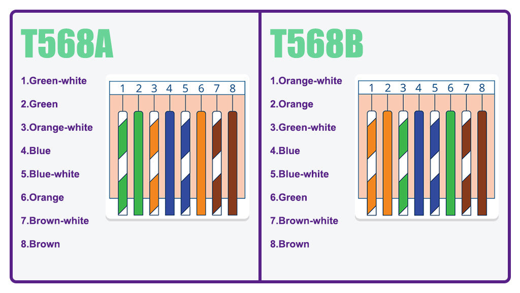
A Cat6 wiring diagram is a visual representation of the precise order in which the eight wires within a Cat6 cable must be arranged when terminating the cable with an RJ45 connector. Adhering to the correct Cat6 cable diagram is paramount to prevent network issues and ensure proper connectivity.
Two primary wiring standards exist for Cat6 cables: T568A and T568B. The key difference between them lies in the swapped positions of the green and orange wire pairs. In practical terms, for most standard network applications, choosing between T568A and T568B wiring color codes is a matter of preference, provided you maintain consistency throughout your network installation. However, T568B has become the more prevalent standard for Cat6 cable termination in modern networking.
Consistency is critical when considering the Cat6 wiring diagram. The chosen wiring standard, whether T568A or T568B, must be applied identically to both ends of the Cat6 cable. Employing T568A on one end and T568B on the other creates a crossover cable. While crossover cables serve specific networking purposes, such as direct device-to-device connections without a switch or hub, standard network setups require straight-through cables with the same wiring diagram on both ends.
 T568A vs T568B wiring diagrams illustrating color code differences
Selecting the Right Cat6 Wiring Diagram: T568A or T568B?
Choosing between the T568A and T568B wiring diagrams depends on several factors:
- Legacy Compatibility (T568A): ANSI/TIA initially recommended T568A for residential installations, primarily due to its backward compatibility with older telecommunications equipment like fax machines and analog phones. If your network needs to interface with such legacy devices, T568A might be the preferred choice.
- Modern Network Standard (T568B): The majority of contemporary network equipment is designed and configured for the T568B color code. For most new installations and modern networking environments, T568B is the more commonly adopted and often recommended standard.
- Existing Infrastructure Consistency: If you are expanding or modifying an existing network, it’s crucial to identify the wiring standard already in use. Maintaining consistency by adhering to the same wiring diagram as the existing infrastructure prevents compatibility issues and simplifies network management.
- Crossover vs. Straight-Through Cables: Traditionally, crossover cables were necessary to connect two similar network devices directly (e.g., computer to computer). However, modern network devices typically support Auto-MDIX (Medium Dependent Interface crossover), which automatically detects and adjusts for cable type. This advancement means straight-through cables, using either T568A or T568B consistently on both ends, are now suitable for almost all connections, reducing the need for crossover cables in most standard network setups.
In most typical scenarios, especially for new installations, T568B is the practical and widely accepted choice for Cat6 wiring.
Step-by-Step Guide: Terminating a Cat6 Cable with T568B Wiring
Now that you understand the Cat6 wiring diagrams, let’s walk through the process of terminating a Cat6 Ethernet cable using the T568B wiring scheme.
Preparation: Tools and Materials
Before starting, gather the necessary tools and materials for efficient Cat6 cable termination:
- Pass-through Cat6 RJ45 Connectors: Pass-through connectors simplify termination, particularly for beginners. They allow wires to extend through the connector, making it easier to verify the wiring order before crimping and reducing errors.
- Strain Relief Boots: These protective boots slide over the RJ45 connector and cable, offering protection against dust, strain, and damage, extending the lifespan of your connections.
- Pass-through RJ45 Crimping Tool: A specialized crimping tool designed for pass-through connectors. These tools provide a clean cut of excess wire and secure crimp in one action.
- Mini Wire Stripper: Essential for safely removing the cable jacket without damaging the internal wires. Choose a stripper with an adjustable blade to accommodate different cable types.
- Cable Snips: Sharp snips for precisely cutting wires, rip cords, and the cable spline.
- Network Cable Tester: Crucial for verifying correct termination and cable functionality after assembly. A tester ensures your connections are properly wired and ready for network use.
Step-by-Step Termination Process:
- Slide on the Strain Relief Boot: Before attaching the RJ45 connector, slide the strain relief boot onto the Cat6 cable. Ensure the boot’s orientation is correct for later insertion into the connector.
 Sliding strain relief boot onto Cat6 cable
- Strip the Cable Jacket: Using the mini wire stripper, carefully remove about 1 inch of the outer cable jacket. Adjust the stripper blade depth to avoid damaging the insulation of the inner wires.
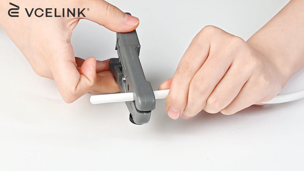 Stripping the outer jacket of a Cat6 cable using a wire stripper
- Cut the Rip Cord and Spline: Locate the rip cord (a thin string under the jacket) and the central spline (plastic divider). Cut these with cable snips to facilitate wire separation and arrangement.
 Cutting rip cord and spline inside Cat6 cable
- Untwist and Straighten Wires: Untwist the four twisted pairs of wires. Straighten each of the eight individual wires using the removed cable jacket as a guide to avoid sharp bends.
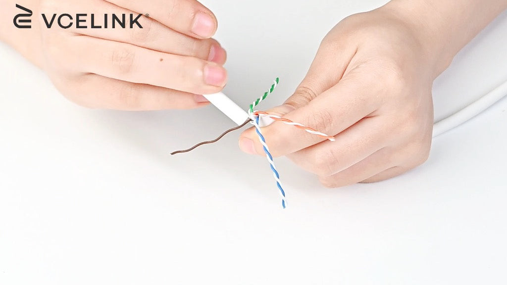 Untwisting and straightening individual copper wires in Cat6 cable
- Arrange Wires in T568B Order: Following the T568B wiring standard, arrange the wires in the correct sequence: Orange-white, Orange, Green-white, Blue, Blue-white, Green, Brown-white, Brown. Verify the order meticulously.
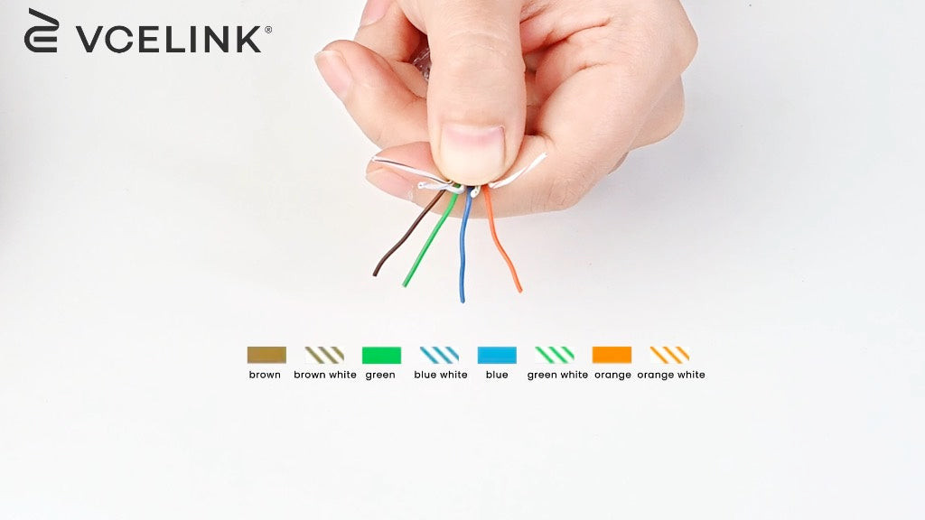 Arranging wires in T568B order for Cat6 termination
-
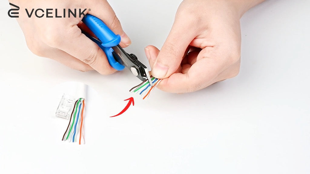
Trim Wires Evenly: Use cable snips to trim the straightened and arranged wires to an even length. An angled cut can facilitate easier insertion into the RJ45 connector.
-
Insert Wires into RJ45 Connector: Carefully insert the wires into the pass-through RJ45 connector, ensuring each wire passes through to the front of the connector in the correct T568B order. Double-check the color sequence at the front of the connector.
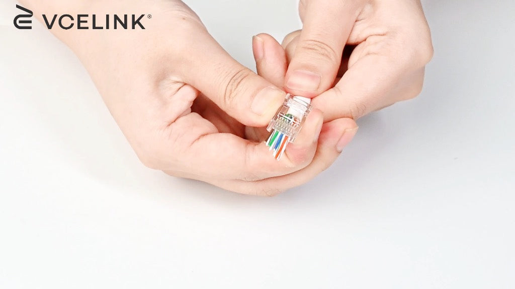 Inserting wires into a pass-through RJ45 connector
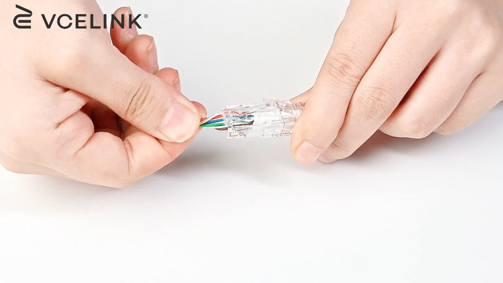
- Verify Wire Order and Seat Boot: Re-verify the wire sequence at the front of the connector to confirm accuracy. Slide the strain relief boot forward to seat it against the RJ45 connector.
 Verifying wire order and seating strain relief boot
- Prepare for Crimping: Gently twist any excess wire extending beyond the connector to facilitate clean insertion into the crimping tool.
 Preparing wires for crimping by twisting excess wire
- Crimp the RJ45 Connector: Insert the connector into the pass-through RJ45 crimping tool. Crimp the connector firmly to secure the wires and trim the excess wire extending through the connector front.
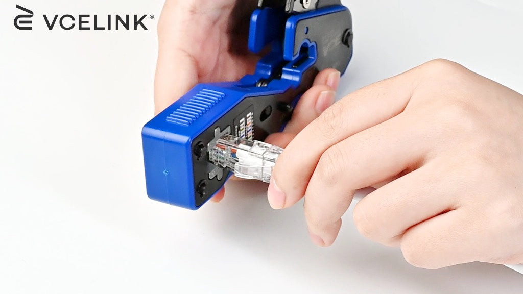 Crimping the RJ45 connector using a pass-through crimping tool
- Terminate the Other End: Repeat steps 1-10 for the other end of the Cat6 cable, ensuring you use the same T568B wiring diagram for a straight-through cable.
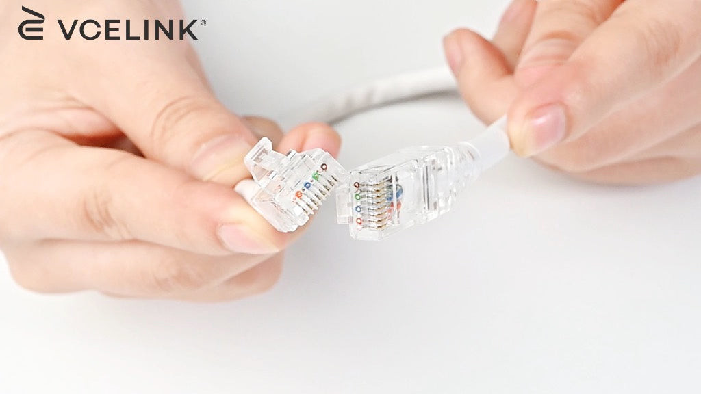 Terminated RJ45 connector on Cat6 cable end
- Test the Cable: Use a network cable tester to verify the continuity and wiring of your newly terminated Cat6 cable. This ensures all wires are correctly connected and the cable is ready for network deployment.
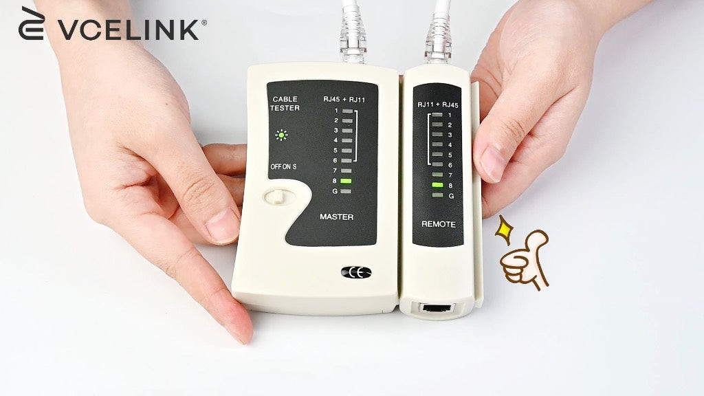 Testing a terminated Cat6 cable with a network cable tester
Common Cat6 Wiring Issues and Best Practices
Even with careful termination, issues can arise, especially for those new to Cat6 cabling. Common problems include:
- Incorrect Wire Order: The most frequent issue is incorrect wire arrangement in the RJ45 connector. Double-checking the T568B (or T568A) sequence before crimping is crucial.
- Poor Contact: Wires not making proper contact with the connector pins can lead to signal loss or network failure. Ensure wires are fully inserted and the crimp is secure.
- Jacket Stripped Too Far Back: Exposing too much of the untwisted wires can increase crosstalk and degrade performance. Strip only the necessary jacket length.
Tips for Successful Cat6 Wiring:
- Use Pass-Through Connectors: These simplify wire order verification and reduce termination errors, particularly for beginners.
- Invest in Quality Tools: A good crimping tool and wire stripper make the process easier and more reliable.
- Practice Makes Perfect: If you are new to cable termination, practice on scrap cable to develop your technique.
- Test Every Cable: Always use a network cable tester to confirm correct wiring and cable functionality before deploying the cable in your network.
- Consider Field Termination Plugs: For on-site repairs or terminations, field termination plugs offer reusability and can be helpful for troubleshooting.
- Shielded Solutions for Noisy Environments: In environments with significant EMI/RFI, using shielded Cat6 cables and connectors is highly recommended to maintain signal integrity.
- Maintain Cable Length Limits: Cat6 cables are specified for runs up to 100 meters (328 feet). Exceeding this length can lead to signal degradation.
- Use Quality Components: Employing high-quality Cat6 cables and connectors ensures reliable performance and longevity.
Conclusion: Mastering Cat6 Wiring for Reliable Networks
Understanding and correctly applying Cat6 wiring diagrams is fundamental for building robust and high-performing Ethernet networks. Whether for home or office environments, mastering Cat6 cable termination empowers you to create custom-length patch cables and ensure reliable network connections. By following this comprehensive guide and practicing good termination techniques, even beginners can confidently handle Cat6 wiring and maintain optimal network performance.
FAQs about Cat6 Wiring Diagrams
Does a Cat6 cable use all eight wires?
Yes, Cat6 cables for Gigabit Ethernet and faster speeds utilize all eight wires. Pairs 1 & 2 and 3 & 6 are used for data transmission and reception, while pairs 4 & 5 and 7 & 8 are used for additional data channels and Power over Ethernet (PoE) applications.
Can I run Cat6 cables in the same conduit as electrical wires?
Running Cat6 cables in the same conduit as electrical wires is generally not recommended due to potential electromagnetic interference (EMI) from power lines. If parallel runs are necessary, maintain a separation of at least 30 cm (12 inches) between unshielded Cat6 cables and power lines. For conduit installations, use shielded Cat6 cables or ensure sufficient physical barriers to separate network and electrical wiring.
What are the consequences of incorrectly wiring a Cat6 cable?
Incorrectly wiring a Cat6 cable can lead to a range of network problems, including complete network failure, reduced network speeds, intermittent connectivity, and data transmission errors. Inconsistent wiring or reversed pairs can significantly degrade signal quality and network performance. Always double-check wiring diagrams and test cables after termination to avoid these issues.
For more in-depth information and resources on network cabling and related topics, explore our blogs. While VCELINK provides valuable general information, it is not a substitute for professional advice tailored to specific situations.